Industrial Pump Repair Canada - Pump and Seal Repair and Replacement Services
ISO 9001 Certified

Industrial Pump Repair Canada - Pump and Seal Repair and Replacement Services
ISO 9001 Certified
A diaphragm pump moves liquid by flexing a membrane inside a chamber. The motion changes chamber volume, drawing fluid through an inlet valve and pushing it out through an outlet valve. No rotating impeller touches the liquid. That distinction matters when a process handles abrasive slurries, viscous fluids, or chemicals that require careful containment.
Pump selection also affects energy use. The U.S. Department of Energy’s Improving Pumping System Performance sourcebook reports that pumping systems can account for 25–50% of energy use in some industrial facilities. That figure covers pumping systems broadly, not diaphragm pumps alone. Still, it highlights why operating conditions, maintenance, and control choices deserve attention. Small details matter.
This guide explains what diaphragm pump systems include and how their parts work together. It follows the fluid path through the suction and discharge strokes, then examines common configurations, applications, and selection factors. Air-operated and mechanically driven models differ in power source and control, even though both rely on diaphragm movement. A pump’s ability to run dry or handle solids also depends on its design and operating limits.
There is no universal best model. A pump that handles a thick coating reliably may perform poorly with another fluid or installation. The overview offers a practical starting point, not a substitute for manufacturer data or a system-specific review. It also considers where diaphragm pumps fit among other positive-displacement options—and where they may not.
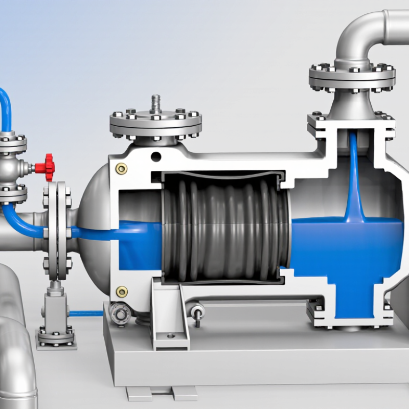
A diaphragm pump system moves liquid by flexing a sealed membrane inside a pump chamber. In an air-operated design, compressed air moves the diaphragm back and forth. This changes the chamber’s volume and pressure. That movement creates suction. Inlet check valves open as liquid enters, while outlet valves remain closed. On the return stroke, the pressure reverses: inlet valves close, and liquid is pushed through the discharge line. The cycle repeats, producing a pulsing flow.
The diaphragm separates the pumped liquid from the drive mechanism, which can help limit leakage and contamination. Materials must suit the fluid’s chemistry and temperature; compatibility should be checked against actual operating conditions, not guessed from appearance.
The flow pulses. A dampener can reduce those pulses where steadier delivery is needed. In practice, restricted suction lines or worn check valves can reduce output, even when the pump still sounds normal.
Inspect the diaphragm and valves during maintenance, especially if flow changes or leakage appears. One detail is easy to overlook: performance depends on the whole system, including air supply, pipe sizing, and the liquid’s viscosity.
What Is a Diaphragm Pump System and How Does It Work?
Key Components and Their Functions
A diaphragm pump system moves liquid through two chambers separated by flexible diaphragms. In an air-operated design, a distribution valve alternately sends compressed air behind each diaphragm. One diaphragm moves outward and draws liquid through an inlet check valve; the other pushes liquid toward the outlet. The check valves act like one-way doors. Small parts matter. In mechanically driven models, a motor and linkage move the diaphragms instead. Both designs rely on the same basic principle: changing chamber volume creates suction and discharge.
The wetted chambers, inlet and outlet manifolds, drive, and piping form the working system. Check valves may use balls or flaps, so solids, viscosity, and orientation can affect their response. A pulsation dampener can smooth the pulsing flow, though it adds another part to inspect. The U.S. Department of Energy’s Improving Pumping System Performance: A Sourcebook for Industry (2006) estimates that pumping systems account for nearly 20% of global electricity demand; that figure covers pumping systems broadly, not diaphragm pumps alone. For operators, pressure, air supply, and diaphragm material deserve attention. A pump can seem correctly sized, yet still perform poorly if its air supply is unstable.
| Component | Main Function | How It Works | Key Operational Note |
|---|---|---|---|
| Power source or drive | Supplies the energy needed to move the diaphragm. | An air-operated pump uses compressed air; mechanically or electrically driven designs use a motor or actuator. | The drive type affects control, installation, and the utilities required. |
| Actuator or air-distribution mechanism | Transfers power to the diaphragm and coordinates its movement. | In an air-operated double-diaphragm pump, a distribution mechanism alternately directs air to each side of the actuator assembly. | Its design varies by pump type; not every diaphragm pump uses compressed air. |
| Diaphragm | Creates changing volume in the pumping chamber and separates the pumped liquid from the drive mechanism. | Moving outward increases chamber volume; moving inward decreases it, producing alternating suction and discharge strokes. | Material selection must suit the fluid, temperature, pressure, and operating conditions. |
| Pump chamber | Holds the fluid during each part of the pumping cycle. | As the diaphragm moves, chamber volume changes and fluid is drawn in or pushed toward the outlet. | Chamber design and wetted materials influence compatibility and cleanability. |
| Suction check valve | Allows fluid to enter the chamber while limiting reverse flow. | It opens when chamber pressure falls below inlet pressure and closes when chamber pressure rises. | Valve type and material should match the fluid and the pump’s intended service. |
| Discharge check valve | Allows fluid to leave the chamber while limiting backflow from the outlet. | It opens when chamber pressure exceeds discharge pressure and closes during the suction stroke. | Check valves are commonly ball-type or flap-type, depending on the pump design. |
| Inlet and outlet manifolds | Connect the pump chambers to the supply and discharge lines. | The inlet manifold distributes incoming fluid; the outlet manifold collects fluid leaving the chambers. | Correct piping and secure connections help prevent leaks and flow restrictions. |
| Housing and fluid-end components | Support the assembly and contain the pumped fluid. | The housing holds components in position, while fluid-end parts form the chambers and flow passages. | Wetted materials should be compatible with the process fluid. |
| Controls and pressure protection | Help regulate operation and protect the system from unsuitable conditions. | Depending on the installation, controls may regulate drive input, while a relief device or bypass arrangement can limit excessive pressure. | Protection requirements depend on the pump, piping, and process design. |
| Operating cycle | Produces a repeating flow of fluid through the pump. | During the suction stroke, the inlet valve opens and fluid enters. During the discharge stroke, the inlet valve closes, the outlet valve opens, and fluid exits. | Double-diaphragm designs alternate the movement of two diaphragms to deliver successive discharge strokes. |
Note: Component names and arrangements vary among air-operated, mechanically driven, and electrically driven diaphragm pumps.
A diaphragm pump moves fluid by flexing a flexible membrane inside a chamber. As the diaphragm pulls back, chamber volume increases and pressure falls. Fluid enters through the inlet check valve, while the outlet valve stays closed. You can picture a small chamber filling like a syringe. The valves guide the flow in one direction.
When the diaphragm pushes forward, chamber volume shrinks. Pressure rises, the inlet valve closes, and fluid passes through the outlet valve. Repeating this motion creates a steady transfer, though the flow often pulses rather than forming a perfectly smooth stream. Some systems use compressed air to move the diaphragm; others use a motor and linkage.
The liquid usually remains separated from the drive mechanism by the membrane, which can help limit leaks and contamination. But “separated” is not the same as “maintenance-free.” Diaphragms and valves wear, especially when handling abrasive fluids or running dry.
A technician should check material compatibility, pressure limits, and valve condition for the actual service. Small details matter: a worn valve may let fluid slip backward, reducing output before a failure looks obvious. Real installations can be less tidy than pump diagrams suggest.
A diaphragm pump moves liquid by flexing a flexible membrane inside a chamber. The drive mechanism supplies that motion. In an air-operated design, compressed air shifts a distribution valve, pushing one diaphragm while the other draws liquid into its chamber. The cycle reverses repeatedly. No rotating shaft contacts the pumped liquid. That can help when handling abrasive fluids, though valve wear and air quality still matter.
Electric and mechanical drives use a motor, crank, or eccentric cam to move the diaphragm. Their stroke rate can often be adjusted with a controller or variable-speed drive. Hydraulic versions use pressurized oil to actuate the membrane and may suit higher-pressure duties. Less noise, sometimes. Each design has limits: check the required flow, pressure, fluid viscosity, and expected operating hours before selecting a drive.
Pump configuration changes performance, too. A single-diaphragm unit delivers flow in pulses; a double-diaphragm arrangement alternates suction and discharge between two chambers, usually smoothing delivery. Pulsation dampeners can reduce pipe movement, but they do not erase every pressure fluctuation. In the workshop, a loose suction hose may cause erratic flow that looks like a pump fault. It is an easy distinction to miss. Review wetted materials, seal options, and maintenance access against the actual fluid and installation, not just the catalog rating.
Check-valve positions during the two strokes of a diaphragm pump cycle
On the suction stroke, the inlet check valve opens while the outlet valve closes, allowing liquid into the chamber. On the discharge stroke, the inlet valve closes and the outlet valve opens, directing liquid out. Values show valve state: 1 = open, 0 = closed.
Diaphragm pump systems move liquid by flexing a diaphragm inside a chamber. The motion alternately draws fluid in and pushes it through discharge valves. Because the pumped liquid can remain separated from moving drive parts, these pumps are useful for transferring chemicals, slurries, wastewater, and food-process liquids when the materials are compatible. They also handle many fluids that contain small solids. Not every model suits every fluid, though.
Operating conditions matter. Check the liquid’s chemical compatibility, temperature, viscosity, and solid-particle size before selecting a pump. Confirm the rated pressure and flow meet the process demand. Suction-line restrictions, air leaks, or long pipe runs can reduce performance. Pulsation may also affect connected instruments and piping, so a pulsation dampener may be appropriate. Verify whether the chosen design permits dry running; assuming all diaphragm pumps do can lead to premature wear. Small details matter.
Tips: Keep the suction line short and adequately sized. Inspect valves and diaphragms for wear, especially after handling abrasive liquids. Watch for unusual vibration, leakage, or changing flow. A simple maintenance log helps reveal patterns, though it will not explain every failure. Check operating limits against actual site conditions.