Industrial Pump Repair Canada - Pump and Seal Repair and Replacement Services
ISO 9001 Certified

Industrial Pump Repair Canada - Pump and Seal Repair and Replacement Services
ISO 9001 Certified
China’s pump industry serves water treatment, construction, agriculture, mining, chemicals, and energy projects worldwide. Buyers often compare flow rate, head, materials, motor efficiency, and price. Yet these specifications do not explain every failure. A pump may be correctly selected but poorly installed, operated outside its best efficiency point, or exposed to unexpected solids.
The International Energy Agency reports that electric motors consume roughly 45% of global electricity. Pumping equipment represents a significant share of that demand in industrial and infrastructure applications. The U.S. Department of Energy also emphasizes system-level assessment, rather than judging a pump by its nameplate alone. This matters when evaluating Chinese suppliers. A small alignment error can create vibration, seal leakage, noise, and rising power bills. A clogged strainer can look like a weak pump. It is not always a pump problem.
This guide explains practical pump system troubleshooting for international buyers sourcing from China. It connects field symptoms with measurable causes, including low discharge pressure, unstable flow, overheating, cavitation, bearing damage, and repeated seal failure. The Hydraulic Institute’s standards provide useful references for pump testing, terminology, and performance evaluation. Buyers should request certified curves, test records, material certificates, spare-parts lists, and clear warranty conditions. Factory audits and witnessed performance tests add valuable evidence, but they cannot replace correct site data.
Some recommendations may require adjustment. Real installations are rarely perfect. Pipe lengths change, water quality varies, and operators sometimes improvise. That uncomfortable detail deserves attention. Reliable purchasing depends on verified data, competent commissioning, and honest communication between the buyer, manufacturer, and service team.
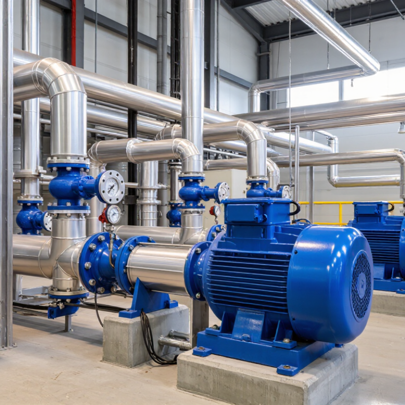
A pump system is more than the pump itself. Each component affects flow, pressure, energy use, and service life. During commissioning inspections, I check the suction pipe before blaming the pump. A blocked strainer, undersized pipe, or trapped air can cause unstable flow and loud vibration.
The pump converts mechanical energy into fluid movement. The motor supplies that energy, while the coupling transfers rotation between both shafts. Suction valves control inlet flow, and discharge valves help regulate operating pressure. Pressure gauges reveal system behavior, but inaccurate gauges can mislead buyers. Small details matter.
Do not overlook seals and bearings. A leaking seal may indicate poor alignment, excessive pressure, or dry running. Bearings need correct lubrication and stable alignment. The control panel protects against overload and can record useful fault information. A surge tank may reduce pressure spikes in changing demand systems.
In practical troubleshooting, I compare actual readings with the approved datasheet and commissioning records. Temperature, vibration, current, flow, and pressure should be checked together. One reading rarely explains the problem. A quiet pump is not always healthy. Sometimes, low noise means restricted flow. I have seen buyers replace a pump when a closed valve caused the real fault. That mistake is understandable, but preventable. Reliable suppliers should explain component roles, testing methods, spare parts, and operating limits clearly.
China Top Pump System Troubleshooting Guide for Buyers
A pump rarely fails without clues. Rising vibration often appears before a bearing or coupling problem becomes obvious. A rattling sound may indicate cavitation, especially when suction pressure falls below the required NPSH margin. Watch the pressure gauge. A sudden drop can point to a blocked strainer, air entering the suction line, or an impeller problem. Seal leakage also deserves attention. A few drops may become a serious safety and maintenance issue. Check motor current, discharge pressure, casing temperature, and flow together. One reading can mislead.
The U.S. Department of Energy’s Improving Pumping System Performance sourcebook reports that pumping systems may consume 25–50% of industrial facility electricity. It also identifies potential energy savings of 20–30% through system improvements. These figures make abnormal operation costly, not merely inconvenient. Buyers should request factory performance curves, vibration limits, material details, and test records. Ask how the supplier verifies flow at the actual duty point. ISO 20816 guidance can support vibration assessment, but it does not replace site testing. A clean test result can still fail to predict poor installation. Misalignment, undersized piping, and frequent dry running remain common oversights. Small details matter. Track readings during startup, normal load, and shutdown. Compare trends, not isolated numbers. Personally, I would treat repeated manual adjustments as a warning sign. The system may be compensating for a design weakness.
A reliable pump troubleshooting process starts with safety, operating records, and clear symptoms. Stop the unit if vibration rises sharply, seals leak, or the motor overheats. Record suction pressure, discharge pressure, flow rate, voltage, current, and fluid temperature. Compare these readings with the approved pump curve. Guesswork often wastes more time than the repair.
Check the system step by step. Inspect the suction valve, strainer, pipe joints, and tank level for blockage or air entry. Then examine rotation direction, coupling alignment, bearing noise, and seal condition. A low discharge flow may indicate cavitation, a closed valve, or an undersized pipe. The U.S. Department of Energy’s Improving Pumping System Performance sourcebook reports that pumping systems can consume 25–50% of industrial facility electricity. Small hydraulic losses matter.
Use trend data before replacing parts. The Hydraulic Institute recommends evaluating pump performance against rated flow, head, and efficiency conditions. A clamp meter can reveal overload, while a vibration reading can expose imbalance or misalignment. However, readings can mislead when instruments are poorly calibrated. Recheck them. Buyers should request test records, material specifications, maintenance history, and a defined acceptance standard such as ISO 9906. One overlooked detail is fluid viscosity. It can change the real operating point, even when the pump appears correctly selected.
A pump that runs loudly, vibrates, or loses pressure needs structured diagnosis. A rattling sound near the suction line often indicates cavitation, restricted flow, or air entering through a loose joint. Check the suction valve, strainer, liquid level, and inlet pressure before replacing components. A hot bearing may reflect misalignment, poor lubrication, or excessive radial load. Measure temperature and vibration at the same operating point.
Low discharge pressure can result from a worn impeller, incorrect rotation, blocked piping, or a pump selected beyond its duty range. Compare actual flow and head with the pump curve. Do not trust pressure alone.
The U.S. Department of Energy reports that pumping systems may consume about 25% of industrial electricity, depending on the facility. Its guidance also identifies potential energy savings of 20% to 50% through system optimization. Small hydraulic errors can therefore create large operating costs.
Buyers should request test records, material specifications, efficiency data, and a corrective-action procedure. Ask whether the supplier verifies performance after installation. In practical inspections, operators often blame the pump first. That assumption is sometimes wrong. A partly closed discharge valve or undersized pipe can imitate mechanical failure. Record sound, vibration, pressure, flow, and motor current together. Field conditions are rarely perfect, and my own early diagnoses have occasionally missed the piping problem.
China Top Pump System Troubleshooting Guide for Buyers?
Reliable replacement parts begin with accurate failure diagnosis. In field inspections, worn mechanical seals often indicate dry running, misalignment, or excessive vibration. Replacing the seal alone may repeat the failure. Check shaft condition, bearing clearance, coupling alignment, and elastomer compatibility before ordering.
The U.S. Department of Energy reports that pumping systems can consume 25–50% of industrial electricity in some facilities. Its pumping-system guidance also identifies potential energy savings of 20–50% through proper assessment and correction. These figures are not universal, but they justify measuring flow, pressure, motor current, and vibration before changing components. Buyers should request material certificates, dimensional tolerances, test records, and traceable batch information. Cheap parts can become expensive downtime.
Preventive maintenance should follow operating conditions, not habit. Record baseline readings after commissioning, then compare them monthly. Inspect seals and couplings during planned stops. Check bearing temperature and vibration trends weekly on critical pumps. Hydraulic Institute guidance supports condition monitoring and correct system operation, rather than relying only on calendar-based replacement. A fixed schedule is convenient, but often wrong. I have seen pumps replaced too early while blocked strainers remained unnoticed. That weakness deserves attention. Use compatible spare kits, but keep one verified emergency set for critical service. Calibration records matter too. Without them, “normal” readings may simply be misleading.
| System Area | Common Symptom | Likely Technical Cause | Recommended Diagnostic Check | Reliable Replacement Part Selection | Typical Acceptance or Operating Reference | Preventive Maintenance Method | Priority |
|---|---|---|---|---|---|---|---|
| Suction Line and Pump Inlet | Pump loses prime, delivers little or no flow, or produces intermittent discharge. | Air leakage at a joint, blocked suction strainer, excessive suction lift, or insufficient liquid level. | Inspect flange gaskets and threaded joints; check the suction strainer; verify liquid level and suction pressure; perform a vacuum or pressure leak test where applicable. | Gaskets, O-rings, suction strainers, isolation valves, and flexible connectors made from materials compatible with the pumped fluid. | Keep the suction line short and airtight. Avoid conditions that cause the available NPSH to fall below the pump's required NPSH. | Clean strainers at scheduled intervals, tighten or reseal joints, and check for air ingress after every suction-side modification. | High |
| Cavitation Control | Crackling or gravel-like noise, vibration, unstable flow, and impeller surface damage. | Insufficient net positive suction head, excessive fluid temperature, clogged suction piping, or operation far from the recommended duty point. | Compare suction conditions with the pump curve; measure suction pressure, discharge pressure, temperature, and flow; inspect the impeller after isolation and depressurization. | Correctly sized impeller, wear rings, suction fittings, and temperature-compatible gaskets. Do not select parts only by external dimensions. | Maintain adequate margin between available and required NPSH. Operate close to the pump's best efficiency region whenever practical. | Monitor noise and vibration trends, keep suction passages clear, and avoid throttling on the suction side. | High |
| Mechanical Seal | Visible leakage from the shaft area, overheating, or repeated seal failure. | Dry running, shaft misalignment, worn shaft sleeve, incorrect seal faces, solids in the fluid, or improper installation. | Check leakage rate, flush or barrier-fluid condition, shaft runout, seal chamber pressure, and installation dimensions. | Seal faces and elastomers selected for fluid chemistry, temperature, pressure, and rotational speed; replace damaged sleeves and springs. | Leakage should remain within the equipment manufacturer's allowable limit. Any sudden increase requires immediate investigation. | Prevent dry running, verify flush flow, inspect seal faces during planned shutdowns, and use clean installation tools and surfaces. | High |
| Bearings and Lubrication | Rising bearing temperature, rumbling noise, high vibration, or shaft looseness. | Insufficient or excessive lubricant, contaminated lubricant, bearing fatigue, poor alignment, or excessive belt and coupling loads. | Measure temperature and vibration; inspect lubricant color and contamination; check shaft play, coupling alignment, and mounting bolts. | Correct bearing type, internal clearance, load rating, seals, and lubricant specification. Use traceable dimensional and material records. | Temperature and vibration must be evaluated against the pump's normal baseline and applicable maintenance limits. A trend increase is more significant than one isolated reading. | Lubricate according to duty and lubricant instructions, keep grease clean, and record temperature and vibration readings over time. | High |
| Coupling and Alignment | Repeated seal or bearing failure, coupling element wear, vibration, or abnormal noise. | Angular or parallel misalignment, soft foot, loose foundation bolts, damaged coupling element, or thermal growth not considered. | Check soft foot, shaft alignment, coupling gap, baseplate condition, and bolt tightness using suitable alignment equipment. | Coupling element with the correct bore, keyway, torque rating, speed rating, and temperature range; replace worn hubs when required. | Alignment should comply with the coupling and equipment tolerance requirements at the expected operating temperature. | Verify alignment after installation, piping work, foundation repairs, and any event that may have moved the pump or motor. | High |
| Impeller and Wear Components | Reduced flow or pressure, increased power consumption, or internal rubbing noise. | Impeller erosion, corrosion, blockage, incorrect rotation, excessive wear-ring clearance, or foreign-object damage. | Confirm motor rotation; compare measured flow and head with the pump curve; inspect impeller passages and measure clearances during shutdown. | Impeller and wear rings with matching hydraulic geometry, balance quality, material grade, and dimensional tolerances. | Replace components when wear clearance, imbalance, cracking, or corrosion exceeds the equipment maintenance limit. | Install upstream filtration where appropriate, inspect solids content, and record clearance measurements during overhauls. | Medium |
| Discharge Piping and Valves | Low discharge pressure, unstable flow, water hammer, or pump overload. | Partially closed valve, blocked discharge line, incorrect valve sizing, air pocket, or a system resistance different from the design condition. | Check valve position, differential pressure, flow rate, line blockage, and pressure fluctuations during start-up and shutdown. | Valves, check valves, gaskets, and expansion joints rated for system pressure, temperature, fluid compatibility, and flow direction. | Operate within the pump's allowable flow range and avoid rapid valve closure that can create damaging pressure surges. | Exercise valves periodically, inspect check-valve movement, and use controlled start-up and shutdown procedures. | Medium |
| Motor and Electrical Supply | Motor does not start, trips overload protection, runs hot, or rotates incorrectly. | Incorrect voltage or phase sequence, unbalanced supply, overloaded pump, poor terminal connection, or inadequate protection settings. | Verify voltage, current on each phase, phase sequence, insulation condition, terminal tightness, and overload settings using qualified personnel. | Motor protection devices, contactors, fuses, cables, and terminal components with suitable voltage, current, short-circuit, and environmental ratings. | Phase current should remain balanced and within the motor nameplate limits under the actual operating load. | Inspect electrical connections, test protection devices, keep motor ventilation clear, and trend operating current. | High |
| Pressure and Flow Instrumentation | Readings are inconsistent, impossible, or different from the actual process condition. | Blocked impulse line, incorrect gauge range, sensor drift, air in the measurement line, or damaged instrument connection. | Compare the instrument with a calibrated reference; inspect impulse lines and isolation valves; check zero reading and connection leakage. | Pressure gauges, transmitters, flow meters, and seals with suitable range, accuracy class, process connection, and fluid compatibility. | Select an instrument range that places normal operation near the middle portion of the scale when practical. | Calibrate at defined intervals, protect instruments from pulsation and freezing, and document calibration results. | Medium |
| Baseplate and Foundation | Persistent vibration after alignment, loose bolts, grout cracking, or pipe strain. | Uneven foundation, soft foot, inadequate grouting, excessive pipe loads, or foundation movement. | Inspect anchor bolts and grout; check baseplate flatness, pipe strain, soft foot, and alignment before and after piping connection. | Anchor bolts, shims, grout materials, vibration isolators, and baseplate hardware suitable for the load and installation environment. | The base should provide stable support without imposing external loads that distort pump or motor alignment. | Inspect foundation condition during planned shutdowns and recheck alignment after any structural or piping work. | Medium |
| Fluid Compatibility | Rapid corrosion, swelling elastomers, discoloration, or unexpected leakage. | Incorrect material selection for pH, chemical concentration, temperature, solids, or fluid contamination. | Confirm fluid composition and temperature; inspect wetted parts; compare material data with a verified compatibility reference. | Wetted components, elastomers, coatings, and fasteners selected for the actual chemical and thermal exposure, not only for water service. | Material suitability must cover normal, minimum, maximum, cleaning, and upset conditions. | Review process changes before implementation and inspect wetted parts for corrosion or swelling during service inspections. | High |
| Spare Parts Purchasing | Replacement part does not fit, fails early, or changes pump performance. | Incorrect model or revision, missing dimensional data, unsuitable material, poor balance, or unverified manufacturing quality. | Match equipment identification, drawing revision, part number, dimensions, material certificate, and inspection records before installation. | Prefer parts with controlled drawings, dimensional inspection, material traceability, balance records where applicable, and documented test results. | Critical dimensions, tolerances, hardness, surface finish, and material grade should conform to the approved technical specification. | Maintain a controlled spare-parts list, label stored parts, protect machined surfaces, and rotate elastomer inventories by shelf life. | High |
| Routine Condition Monitoring | Small problems become unplanned shutdowns or expensive secondary damage. | No baseline data, irregular inspections, delayed response to trends, or incomplete maintenance records. | Track flow, pressure, current, temperature, leakage, vibration, and operating hours; compare readings with the established baseline. | Calibrated measurement tools, vibration sensors, temperature probes, inspection gauges, and service kits appropriate for the pump duty. | Use trend changes and deviations from normal operating values to schedule corrective action before functional failure. | Perform daily visual checks, weekly or monthly condition checks according to duty, and documented major inspections at planned intervals. | Low |