Industrial Pump Repair Canada - Pump and Seal Repair and Replacement Services
ISO 9001 Certified

Industrial Pump Repair Canada - Pump and Seal Repair and Replacement Services
ISO 9001 Certified
Designing a reliable pump system in 2026 starts with the fluid, not the catalogue. Engineers must define flow rate, total dynamic head, temperature, viscosity, solids, and operating hours before selecting equipment. A clear duty point prevents costly oversizing. It also exposes uncertain assumptions early. Good design is practical.
This guide explores pump system design through field-tested principles and current engineering practice. It considers variable-speed drives, high-efficiency motors, sensor feedback, digital monitoring, and maintainability. A pump may look efficient on a test sheet yet waste energy through throttled valves, poor pipe sizing, or frequent cycling. Site measurements matter. A pressure gauge that fluctuates beside a warm bearing can reveal more than a polished specification. Designers should verify NPSH margins, minimum flow protection, seal compatibility, control logic, and access for lifting. Safety interlocks and documented commissioning procedures remain essential, regardless of how advanced the software becomes.
The discussion also addresses lifecycle cost, carbon reduction, cybersecurity for connected controls, and responsible compliance with applicable standards. Manufacturer data, independent calculations, and experienced review should support each major decision. No model predicts every site condition. Rain, sediment, operator habits, and future expansion can challenge a perfect spreadsheet. That is where judgment matters. Readers will find a structured approach, but not a magic formula. Recheck the assumptions. Then improve the design.

Pump design begins with the job the system must perform. Will it transfer clean water, circulate heated liquid, or handle suspended solids? The answer affects materials, impeller design, sealing, and maintenance access. In practical assessments, I record the process objective beside the pump location. This simple note prevents a common mistake: selecting equipment before understanding the process.
Define the required flow rate with measured demand, not optimistic guesses. Record normal, minimum, and peak flow conditions. Then calculate total dynamic head, including elevation, pipe friction, valves, filters, and discharge pressure. A neat spreadsheet can still lie. I have seen designs fail because a partially closed valve was ignored. Allowing a reasonable operating margin helps, but excessive margin wastes energy and may create unstable operation.
Operating conditions need equal attention. Document liquid temperature, viscosity, density, vapor pressure, corrosiveness, solids content, and possible air entry. Check suction piping carefully, then compare available NPSH with the pump’s requirement. Small changes in temperature can reduce the safety margin. Specify the duty point clearly, including flow, head, speed, and expected run hours. Leave assumptions visible for later review. The first estimate is often wrong. Testing the actual flow after installation may reveal a quieter, more useful correction than another round of calculations.
A dependable pump design starts with Total Dynamic Head, not motor size. TDH combines static lift, pressure requirements, pipe friction, fittings, and velocity head. Measure the elevation difference from the liquid surface to the delivery point. Then calculate friction losses using pipe length, internal diameter, flow rate, and fluid properties. Include elbows, valves, filters, and check valves. Small details matter.
Convert required outlet pressure into metres of liquid head. Record every assumption in a calculation sheet. My early designs often underestimated filter fouling. That mistake reduced flow within months. Test results should replace guesses whenever possible.
Select the pump from its performance curve at the duty point, not at maximum flow. A centrifugal pump suits steady water transfer and moderate viscosity. A positive-displacement pump fits dosing, high pressure, or thicker fluids. A submersible pump can simplify drainage from a flooded pit.
Check efficiency, motor loading, control range, and NPSH available. Leave a reasonable operating margin, but avoid oversized pumps. Oversizing can cause throttling, noise, wasted energy, and unstable operation.
Site conditions may change. Recheck the design after commissioning.
How to Design a Pump System in 2026?
Design Piping, Valves, Controls, and Supporting Components
A reliable pump system starts with the whole network, not the pump alone. Pipe diameter, route length, fittings, and elevation define total dynamic head. The U.S. Department of Energy reports that pumping systems can represent 25% to 50% of industrial motor energy use. Small design errors can become permanent energy losses.
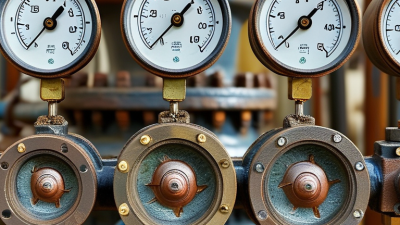
Use smooth pipe routes and reduce unnecessary elbows. Size the suction line carefully. High velocity can increase friction and raise the risk of cavitation. Install isolation valves where maintenance requires them. Place check valves according to flow direction and water hammer risk. A pressure gauge near the pump discharge can reveal problems that software may miss.
Tips: Measure actual flow and pressure during commissioning. Do not trust assumptions alone. Record valve positions, vibration, and motor load.
Variable-speed controls can match pump output to changing demand. However, poor control logic may create unstable operation. The International Energy Agency identifies motor-driven systems as a major source of industrial electricity demand, making control quality financially important. Use sensors at meaningful locations, not simply near the easiest cable route. Protect instruments from heat, moisture, and vibration.
Supporting components deserve equal attention. Include strainers, air-release devices, flexible connectors, foundations, and accessible drains. The Hydraulic Institute recommends reviewing the entire system curve before final selection. I would also leave room for human error. Operators may close a valve too quickly. Maintenance teams may bypass a sensor. A design that works only under perfect conditions is not finished.
| Design Area | Component or Parameter | Representative Design Data | Engineering Basis | Selection or Sizing Guidance | Required Check or Deliverable |
|---|---|---|---|---|---|
| 1. Design Basis and Hydraulic Duty | |||||
| Process duty | Normal flow rate | 180 m³/h | Use the normal operating demand for the primary duty point. | Confirm the pump operates near its best efficiency point at normal flow. | Design-basis document and duty-point schedule |
| Process duty | Maximum flow rate | 220 m³/h | Allow for peak demand, control-valve tolerance, and expected operating variation. | Verify that the selected pump and motor can meet the maximum required flow without excessive throttling. | Maximum-flow hydraulic case |
| Process duty | Total dynamic head | 48 m at normal flow 55 m at maximum flow |
Total dynamic head includes static elevation, friction loss, equipment loss, and required terminal pressure. | Calculate the complete system curve rather than selecting the pump from static head alone. | System-curve calculation |
| Fluid properties | Water at approximately 20°C | Density: 998 kg/m³ Dynamic viscosity: 1.00 mPa·s |
Fluid properties directly affect hydraulic losses, power, Reynolds number, and NPSH requirements. | Recalculate the design for the minimum and maximum operating temperatures when applicable. | Fluid-property table |
| Operating cases | Minimum continuous flow | 90 m³/h | Operation below the pump's stable range can cause recirculation, vibration, and overheating. | Provide a minimum-flow recycle line or automatic control if the process can operate below the pump's minimum stable flow. | Minimum-flow protection philosophy |
| System curve | Static and friction components | Static head: 24 m Estimated friction and equipment losses at normal flow: 18 m Terminal pressure allowance: 6 m |
Head losses vary approximately with the square of flow in turbulent flow. | Use verified pipe lengths, fittings, valves, strainers, heat exchangers, and elevation data. | Hydraulic profile and loss summary |
| 2. Pump Selection and Mechanical Arrangement | |||||
| Pump selection | Configuration | Two pumps, one duty and one standby | Parallel standby capacity improves availability for a critical transfer service. | Each pump should independently satisfy the required duty unless a reduced-capacity operating philosophy is approved. | Pump operating philosophy |
| Pump selection | Best efficiency point | Target normal operation within approximately 80–110% of BEP flow | Operation close to BEP generally reduces radial loads, vibration, and internal recirculation. | Review the complete performance curve, including efficiency, power, NPSH required, and allowable operating range. | Certified pump performance curve |
| Pump selection | Motor rating | Calculated absorbed power: approximately 34 kW Preliminary motor rating: 45 kW |
Motor rating should cover maximum absorbed power over the operating range, including fluid-property and voltage variations. | Check motor service factor, starting method, ambient conditions, and available electrical supply. | Motor load and starting assessment |
| Pump selection | Speed control | Variable-speed range: approximately 35–50 Hz | Changing speed changes flow approximately in proportion to speed, head with the square of speed, and power with the cube of speed. | Confirm minimum speed does not cause inadequate cooling, unstable operation, or operation below the manufacturer's approved range. | Affinity-law and operating-envelope review |
| Pump selection | Materials and seals | Wetted metal: suitable corrosion-resistant alloy Seal arrangement: single mechanical seal for clean water service |
Materials must be compatible with fluid chemistry, temperature, solids content, and cleaning chemicals. | Specify seal elastomers, shaft material, wear components, and corrosion allowance from the process data. | Material compatibility schedule |
| Installation | Pump orientation and access | Horizontal arrangement with removable coupling guard and maintenance clearance | Safe access is required for seal, bearing, coupling, and motor maintenance. | Provide lifting points, drain access, alignment access, and sufficient clearance for component removal. | Equipment layout and maintenance envelope |
| 3. Piping Design | |||||
| Suction piping | Nominal pipe size | DN250 for approximately 180 m³/h | At 180 m³/h, the approximate internal velocity is 1.0 m/s for a 250 mm internal diameter. | Keep suction velocity moderate and minimize fittings, abrupt reducers, and high points that can trap air. | Suction-line hydraulic calculation |
| Discharge piping | Nominal pipe size | DN200 for approximately 180 m³/h | At 180 m³/h, the approximate internal velocity is 1.6 m/s for a 200 mm internal diameter. | Balance capital cost against friction energy, noise, water hammer, and future capacity requirements. | Discharge-line hydraulic calculation |
| Suction piping | Reducer arrangement | Eccentric reducer, flat side on top for a horizontal suction line | This arrangement helps prevent an air pocket from forming at the pump suction. | Use a reducer geometry that maintains uniform velocity and avoids a sudden contraction immediately at the nozzle. | Piping isometric and nozzle-load review |
| Piping layout | Straight-run and flow conditioning | Provide a smooth approach to the suction nozzle; avoid closely spaced elbows and tees | Uneven velocity distribution at the impeller eye can increase vibration and reduce pump performance. | Follow the pump manufacturer's suction-piping requirements and verify the effect of upstream fittings. | Suction arrangement drawing |
| Pipe flexibility | Thermal expansion | Evaluate for a design temperature range of approximately 5–80°C | Thermal movement can impose excessive loads on pump nozzles and supports. | Use guided supports, anchors, loops, or engineered flexibility; do not use the pump casing to absorb pipe movement. | Pipe-stress analysis and support plan |
| Pipe integrity | Pressure rating | Preliminary design pressure: 10 bar(g) Final rating to include surge pressure |
Operating pressure alone does not define the required pressure class. | Check hydrostatic test pressure, shutoff head, relief settings, transient pressure, temperature derating, and flange rating. | Line list and pressure-design calculation |
| 4. Valves and Inline Equipment | |||||
| Suction isolation | Isolation valve | Full-port resilient-seated butterfly or gate valve | The valve should provide isolation with minimal pressure loss during normal operation. | Do not use the suction isolation valve for routine flow control; keep it fully open during pump operation. | Valve data sheet and operating procedure |
| Suction protection | Strainer | Temporary start-up strainer where construction debris is possible | Permanent suction strainers can create excessive pressure loss and reduce available NPSH if not properly sized. | Provide differential-pressure monitoring and a cleaning plan; remove temporary strainers after commissioning when appropriate. | Strainer specification and cleaning procedure |
| Discharge protection | Check valve | Non-slam check valve located near the pump discharge | Prevents reverse rotation and limits reverse flow when the pump stops. | Select for low pressure loss and stable closure; assess closing time against the system transient response. | Check-valve selection and surge review |
| Discharge isolation | Isolation valve | Full-port butterfly or gate valve downstream of the check valve | Allows pump removal and maintenance without draining the complete system. | Provide adequate spacing for removal and ensure the valve is not used as an uncontrolled throttling device. | Valve arrangement drawing |
| Flow control | Control valve or variable-speed drive | Preferred primary control: variable-speed drive Secondary trim: control valve where required |
Speed control can reduce throttling losses when the process has variable flow demand. | Size the control valve for stable authority and verify that the pump remains within its allowable operating region. | Control-valve sizing and control narrative |
| Pressure protection | Pressure relief or bypass arrangement | Set point below the weakest component's allowable pressure | Protection is required where blocked discharge, thermal expansion, or pump shutoff head can exceed the design pressure. | Discharge relief should return to a safe destination and should not discharge into a location that can cause recirculation hazards. | Relief-device calculation and discharge route |
| Drainage and venting | Drain and air-release valves | Low-point drains and high-point automatic air release where required | Air pockets reduce capacity and can cause noise, vibration, and loss of prime. | Route drains to a safe collection system and provide isolation for maintenance. | Drain-and-vent schedule |
| 5. Controls, Instrumentation, and Protection | |||||
| Flow control | Flow transmitter | Magnetic flow meter for conductive, clean liquid service | Flow feedback supports process control, minimum-flow protection, performance monitoring, and energy optimization. | Install with a full pipe, appropriate grounding, and sufficient straight-run or approved flow conditioning. | Instrument data sheet and installation detail |
| Pressure monitoring | Suction and discharge pressure transmitters | Typical calibrated range: 0–10 bar(g) | The pressure difference provides an operational indication of pump head and can identify blocked lines or degraded performance. | Use root valves, pulsation-free impulse connections, and isolation provisions for calibration. | Instrument index and alarm set-point list |
| Pump protection | Low suction-pressure trip | Alarm and trip based on minimum allowable suction pressure and NPSH margin | Low suction pressure can lead to cavitation, loss of prime, or pump damage. | Set points must be based on the actual pump curve, fluid temperature, suction elevation, and transient conditions. | Cause-and-effect matrix |
| Pump protection | Minimum-flow protection | Automatic recycle initiated below approximately 90 m³/h | Protects against overheating and internal recirculation during low-demand operation. | Size the recycle path for the manufacturer's minimum continuous stable flow at the expected head. | Recycle-valve sizing and logic diagram |
| Mechanical condition | Vibration and bearing-temperature monitoring | Continuous monitoring for critical service; periodic measurement for non-critical service | Increasing vibration or temperature can indicate misalignment, cavitation, imbalance, bearing damage, or pipe strain. | Establish alert and shutdown values from applicable machinery standards and the pump manufacturer's limits. | Condition-monitoring plan |
| Motor control | Variable-speed drive | Rated for a 45 kW motor with suitable overload and harmonic provisions | The drive provides controlled acceleration, process modulation, and reduced starting stress. | Verify bypass requirements, electromagnetic compatibility, motor insulation, cooling at low speed, and emergency-stop behavior. | Motor-control schematic and drive settings |
| Automation | Duty/standby sequencing | Automatic changeover on trip or scheduled operating hours | Alternating pumps balances runtime and keeps the standby pump available. | Include permissives for valve position, low tank level, motor availability, and confirmed flow before declaring successful start. | Control narrative and PLC logic |
| 6. NPSH, Transients, Supports, and Commissioning | |||||
| Cavitation prevention | Available NPSH | Example available NPSH at normal operation: 8.5 m | NPSH available depends on absolute suction pressure, liquid vapor pressure, static elevation, and suction-line losses. | Calculate NPSH available at maximum liquid temperature and minimum tank level, not only at normal conditions. | NPSH calculation for all operating cases |
| Cavitation prevention | NPSH margin | Example pump NPSH required: 5.0 m Example margin: 3.5 m |
A positive margin is required, but the appropriate margin depends on pump type, service criticality, and operating variability. | Use the pump manufacturer's recommended margin and verify performance at the maximum flow and temperature case. | NPSH margin statement |
| Transient control | Water hammer assessment | Review pump trip, rapid valve closure, check-valve closure, and power failure cases | Transient pressure can exceed steady-state design pressure even when operating conditions appear acceptable. | Use a surge vessel, controlled valve closure, flywheel, soft stop, or other engineered measure when required by the analysis. | Transient hydraulic model and mitigation design |
| Equipment support | Baseplate and foundation | Rigid grouted foundation with adequate mass and anchor-bolt capacity | Foundation stiffness affects alignment, vibration, and long-term equipment reliability. | Design for operating weight, rotating forces, piping loads, seismic effects where applicable, and maintenance loads. | Foundation drawing and anchor-bolt plan |
| Pipe supports | Support spacing and restraint | Support spacing based on pipe material, diameter, fluid weight, insulation, and allowable deflection | Unsupported piping can transfer excessive moments to pump nozzles and cause flange leakage. | Provide independent supports near the pump, guides for thermal movement, and restraints for transient loads. | Pipe-support schedule and nozzle-load check |
| Alignment | Coupling alignment | Cold alignment adjusted for operating temperature and verified after piping connection | Thermal growth and pipe strain can change shaft alignment after installation. | Perform soft-foot, angular, and parallel-offset checks using calibrated alignment equipment. | Alignment report |
| Commissioning | Pre-start checks | Flush piping, clean strainers, confirm rotation, open suction valve, prime pump, and verify seal system | Foreign material, incorrect rotation, closed valves, or inadequate priming can damage the pump during the first start. | Use a signed pre-start checklist and confirm that the pump is never operated dry. | Pre-commissioning checklist |
| Performance verification | Acceptance test | Record flow, suction pressure, discharge pressure, speed, motor power, vibration, and temperature | Measured data establishes the installed baseline for future troubleshooting and maintenance. | Compare the measured duty point with the approved pump curve and document deviations. | Commissioning and performance-test report |
Pump design in 2026 should begin with energy, safety, reliability, and maintenance. The U.S. Department of Energy reports that pumping systems can consume about 25% of industrial electricity. Its Pumping System Assessment Tool also indicates potential savings of 20–50% in inefficient systems. These figures justify measuring flow, pressure, operating hours, and power before selecting equipment. A smaller pump is not automatically more efficient. Oversized pumps often throttle through valves, wasting energy as heat and noise.
Use measured duty points, not optimistic assumptions. Select a pump near its best efficiency point, then check low-flow, peak-flow, and emergency conditions. Include soft-start control, pressure relief, dry-run protection, isolation valves, and accessible drains. A 2024 International Energy Agency efficiency report highlights motor-driven systems as a major global electricity load. Therefore, motor efficiency and control strategy deserve equal attention. Safety also includes guarding rotating parts and controlling leakage around seals.
Maintenance planning should be designed into the pipework. Leave space for bearing inspection, seal replacement, lifting access, and safe lockout. Condition monitoring can track vibration, temperature, current, and unusual pressure changes. The Hydraulic Institute recommends evaluating system interaction, not just pump curves. That matters in real facilities. A clean calculation may still miss seasonal fouling or unstable demand. I would review actual operating data after commissioning, because the original design may be wrong. Small corrections early are usually cheaper than repeated failures.
A pump system in 2026 should be designed as a measurable system, not a collection of isolated components. Field experience shows that friction, poor control logic, and oversized pumps often appear after commissioning. The U.S. Department of Energy notes that pumping can consume 25–50% of industrial energy in some facilities. That range deserves attention.
Validate the design with a factory test and a site acceptance test. Measure flow, discharge pressure, suction pressure, motor power, vibration, and temperature. Compare each result with the design duty and ISO 9906 acceptance criteria. Test it cold. Then test it at normal operating temperature. A system may pass one condition and fail another. Check the available net positive suction head during the worst credible operating case. Small suction losses can create large reliability problems.
Monitoring should continue after handover. Install calibrated sensors at practical access points, not hidden behind insulation or crowded pipework. The International Energy Agency’s Energy Efficiency 2024 analysis identifies motor-driven systems as a major global efficiency opportunity, with electric motors using roughly half of global electricity. Track specific energy in kilowatt-hours per cubic metre, not only pressure. A rising value can reveal throttling, fouling, leakage, or control drift. Optimize gradually. Adjust setpoints, trim impellers only after verification, and review operating hours against demand. My first design reviews focused too heavily on peak flow. That was incomplete. Real systems spend more time away from peak duty, where monitoring exposes the expensive mistakes.