Industrial Pump Repair Canada - Pump and Seal Repair and Replacement Services
ISO 9001 Certified

Industrial Pump Repair Canada - Pump and Seal Repair and Replacement Services
ISO 9001 Certified
Choosing a Distributed Power Generation Gearbox is a practical engineering decision, not a catalogue exercise. The correct unit must match the generator’s torque, speed, load pattern, and operating environment. A gearbox serving a biogas plant may face sudden load changes, while a solar tracking system demands quieter, slower, highly precise movement. These conditions are not interchangeable.
John Moubray, a respected reliability and maintenance expert, wrote, “The consequence of a failure determines the maintenance strategy.” That principle applies directly to gearbox selection. Engineers should examine failure consequences before comparing ratios or prices. A failed gearbox can stop generation, damage connected equipment, and create expensive downtime. Reviewers should check thermal capacity, bearing design, lubrication access, sealing quality, vibration limits, and manufacturer test records. Ask for evidence.
Field experience matters.
A well-designed gearbox may still underperform when alignment is poor, oil selection is wrong, or maintenance intervals are unrealistic. This is where many specifications become overly optimistic. Real installations collect dust, moisture, heat, and operator mistakes. Those details deserve attention.
The best choice balances efficiency, service life, maintainability, and total ownership cost. It should also fit the generator frame, coupling, brake system, and control strategy. Independent inspection can strengthen confidence, especially for critical installations. No selection is perfect. However, a transparent review of operating data can expose weak assumptions before they become mechanical failures. This guide explains how to compare options carefully and choose a Distributed Power Generation Gearbox with dependable performance in the field.
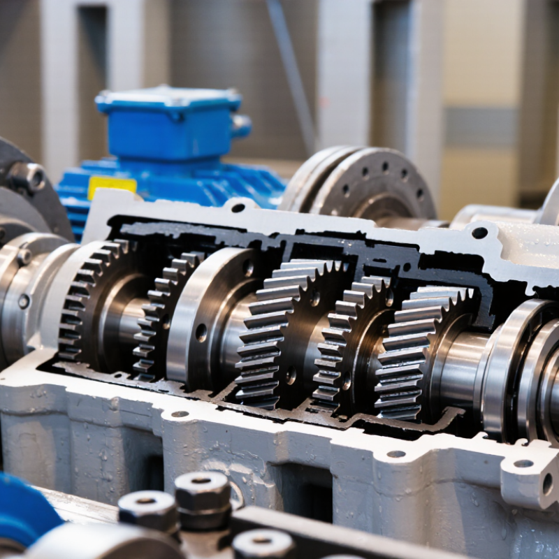
A gearbox should match the real operating profile, not only the generator’s rated power. Record continuous power, peak demand, shaft speed, torque, and operating hours. Include startup loads and sudden load changes. These events often expose weak assumptions.
Check the installation environment carefully. A coastal site may expose the gearbox to salt and moisture. A remote solar plant may face dust, high temperatures, and limited maintenance access. Altitude can reduce cooling performance. Measure ambient temperature, humidity, vibration, and available space before selecting the transmission ratio.
The generator connection also matters. Confirm input and output speeds, rotation direction, shaft alignment, and coupling limits. A gearbox running near its maximum rating may work on paper, yet fail under repeated overloads. Add a suitable service factor for fluctuating loads and frequent starts. Do not guess.
In practice, engineers should compare the expected load curve with the gearbox torque curve. Pay attention to low-speed operation, where lubrication and cooling may become less effective. Specify acceptable noise, efficiency, backlash, and emergency shutdown conditions. Maintenance plans deserve equal attention. If technicians can inspect oil levels easily, small problems may be found earlier.
A spreadsheet cannot capture every site condition. That is worth remembering. Allow room for uncertain weather, imperfect alignment, and future power demand. Reliable selection comes from measured data, cautious assumptions, and review by qualified mechanical and electrical professionals.
Choosing a distributed power generation gearbox starts with the generator, prime mover, and site load. A helical gearbox suits steady duty, compact layouts, and efficient power transfer. A planetary design handles high torque in a smaller housing, but inspection can be less convenient. Bevel-helical units help when input and output shafts must meet at an angle. I have seen compact equipment favor density, then struggle with heat removal. That trade-off deserves attention.
The ratio should match speed, torque, frequency, and the generator’s operating range. A high ratio can reduce generator speed requirements, yet it increases gearbox torque. A lower ratio may improve response, but it can demand a larger generator or faster prime mover. Calculate rated and transient loads, not only average power.
For example, 1,800 rpm input and 900 rpm output require a 2:1 reduction. Real losses change the required rating.
Select service factors from measured duty cycles, starts, stops, and grid events.
Transmission configuration also affects reliability. Direct inline arrangements usually simplify alignment and maintenance. Parallel-shaft layouts can support offset equipment and flexible installation. Right-angle arrangements save space, though bearings and lubrication require careful review. Single-stage systems may reduce losses, while multistage systems achieve larger ratios in manageable steps. Specify backlash, torsional stiffness, cooling, seals, and monitoring points before approval.
Do not trust catalog ratings alone. Field temperature, dust, vibration, and imperfect alignment can change performance. A gearbox that looks efficient on paper may disappoint beside a hot, dusty generator.
Evaluate Load Capacity, Efficiency, Reliability, and Service Life
Selecting a distributed power generation gearbox starts with the real operating load, not only the generator’s rated output. Measure continuous torque, peak torque, speed changes, and daily duty cycles. A gearbox may handle the average load yet fail during frequent starts or sudden grid changes. Measure the real load. Check the service factor against documented calculations, not sales estimates.
Efficiency affects fuel use, heat, and operating cost. Compare rated efficiency across the expected speed range, because laboratory peak values can mislead. Inspect gear geometry, bearing quality, lubrication method, and cooling capacity. Heat exposes weak designs. During commissioning, record oil temperature, vibration, noise, and shaft alignment. These readings create a useful baseline for future maintenance.
Reliability depends on more than strong gears. Ask for fatigue calculations, material records, quality inspections, and test procedures. Confirm whether seals and bearings suit dust, humidity, and temperature at the installation site. Service life should include lubrication intervals, inspection access, spare-part availability, and realistic repair times. I once treated a quiet gearbox as a healthy gearbox; later, vibration data showed early alignment trouble. That mistake reinforced a simple lesson: field measurements deserve more trust than appearance. Small errors matter. Choose a design that remains stable under variable loads and can be inspected before damage becomes expensive.
Choosing a distributed power generation gearbox starts with the generator, not the gearbox catalog. Match rated speed, torque, shaft direction, coupling dimensions, and allowable torsional vibration. A 1,500-rpm generator may need a different ratio than a 1,800-rpm unit, even at similar power. Confirm peak torque during starting and sudden load changes. Do not size only from continuous output. That shortcut fails.
The prime mover changes the duty cycle. Gas engines, diesel engines, and turbines create different pulsations, temperatures, and transient loads. Ask for the engine’s firing frequency, overspeed limit, and stopping method. Then check the gearbox service factor against the actual operating profile. In field reviews, I compare drawings with measured vibration and oil temperatures. Paper data can be incomplete. Small details matter. A flexible coupling may reduce shock, but it cannot correct poor alignment or an unsuitable shaft design.
Site conditions deserve equal attention. High altitude reduces cooling capacity; dust can block air paths, while humidity accelerates corrosion. Specify enclosure protection, filtration, oil viscosity, cooling method, and heater requirements. Consider foundation stiffness, ambient noise limits, access for oil changes, and lifting space. I once treated maintenance clearance as a minor detail; later, a cramped installation made routine inspection needlessly difficult. Check grid frequency, load steps, and emergency operation with the system integrator. Leave a documented margin for uncertainty, but avoid excessive oversizing, which can reduce efficiency and raise cost.
| Prime Mover / Application | Typical Input Speed | Generator Compatibility | Typical Gearbox Function | Key Load and Duty Requirements | Important Site Conditions | Essential Selection Checks |
|---|---|---|---|---|---|---|
| Diesel engine generator | Typically 1,500 rpm at 50 Hz or 1,800 rpm at 60 Hz for four-pole generators | Synchronous or induction generator; direct coupling is common when speeds match | Speed matching, offset transmission, or right-angle power transfer | High torsional excitation, cyclic torque, frequent starts, and rapid load changes | Dust, outdoor temperature variation, vibration, limited maintenance access, and possible noise restrictions | Check torsional natural frequencies, coupling alignment, starting torque, service factor, lubrication temperature, and emergency-stop loads |
| Natural-gas or biogas engine generator | Commonly 1,000–1,800 rpm, depending on engine size and electrical frequency | Synchronous generator is frequently used for stable voltage and power-factor control | Usually speed matching or mechanical layout adaptation rather than a large ratio increase | Continuous-duty operation, combustion-induced torsional vibration, and possible overload during grid disturbances | High ambient temperature, corrosive or wet biogas, explosive-atmosphere classification, and ventilation requirements | Confirm gas composition, enclosure classification, shaft sealing, oil compatibility, continuous thermal rating, and vibration limits |
| Small hydro turbine | Approximately 75–1,000 rpm, depending on head, flow, and turbine type | Synchronous generator for fixed-frequency output or induction generator for simpler grid-connected systems | Raises turbine speed to the generator speed; parallel-shaft, bevel, or planetary layouts may be used | High starting torque, continuous operation, hydraulic transients, and possible overspeed after load rejection | High humidity, water ingress, corrosion, sediment, low temperatures, and difficult access | Check overspeed rating, thrust and radial loads, shaft deflection, sealing, corrosion protection, and drainage provisions |
| Wind turbine generator | Rotor speed commonly 10–30 rpm for larger low-speed turbines; generator speed depends on the drivetrain | High-speed asynchronous or synchronous generator, often combined with a power converter | Large speed increase, often using planetary and parallel-stage gearing | Variable torque, reversing loads, cyclic bending, transient gusts, braking loads, and fatigue duty | Wind, rain, salt spray, low temperature, lightning, tower vibration, and limited service access | Evaluate fatigue life, peak torque, bearing loads, overspeed protection, thermal balance, sealing, and condition monitoring |
| Microturbine generator | Often approximately 30,000–100,000 rpm at the turbine shaft | High-speed permanent-magnet generator with an electronic power converter | Usually no mechanical gearbox; a gearbox is considered only for a specific mechanical interface | Very high speed, low shaft torque, strict rotor balance, and tight bearing or lubrication requirements | High inlet-air temperature, dust filtration, acoustic limits, and sensitive electronic equipment | Confirm whether a gearbox is necessary; check critical speed, balance grade, overspeed containment, and converter compatibility |
| Biomass steam turbine | Typically 3,000 rpm at 50 Hz or 3,600 rpm at 60 Hz for two-pole generator systems; turbine speed may differ | High-speed synchronous generator or geared generator arrangement | Reduces or increases speed to match the selected generator and turbine operating point | High-speed continuous duty, thermal expansion, steam admission transients, and overspeed events | High ambient temperature, hot pipework, moisture, dust, and fire-protection requirements | Check thermal growth, oil-system cooling, high-speed bearing life, overspeed trip, steam leakage protection, and rotor dynamics |
| Selection Parameter | Recommended Engineering Check | Why It Matters |
|---|---|---|
| Gear ratio | Ratio ≈ input speed ÷ required generator speed; verify the full operating-speed range | The generator must operate within its rated electrical frequency and mechanical speed limits |
| Torque capacity | Torque in N·m = 9,550 × power in kW ÷ speed in rpm; apply transient and service factors | Rated torque alone may not cover starting, short-circuit, grid-trip, or load-rejection events |
| Generator interface | Verify shaft diameter, key or spline, flange dimensions, rotation direction, coupling type, and allowable overhung load | Mechanical incompatibility can cause misalignment, excessive bearing loads, or premature failure |
| Torsional behavior | Perform a torsional vibration analysis for the complete prime mover–gearbox–generator train | Resonance can produce severe alternating torque, gear damage, coupling failure, and excessive noise |
| Environment and protection | Define ambient temperature, altitude, humidity, dust, corrosion, ingress protection, and hazardous-area requirements | Environmental derating and sealing requirements directly affect thermal capacity and service life |
| Maintenance and monitoring | Specify oil filtration, temperature sensors, vibration monitoring, inspection access, and spare-part strategy | Distributed sites often have limited personnel and high costs associated with unplanned downtime |
Maintenance needs should match the site, not an ideal laboratory schedule. Check oil sampling intervals, filter access, seal inspection points, and vibration monitoring options.
Inspect it cold. Small leaks matter. In a remote plant, a gearbox needing specialist tools can create expensive downtime.
I have seen minor alignment errors become serious bearing damage after repeated temperature changes.
Ask for clear procedures, recommended lubricants, spare-part lists, and realistic service intervals. These details reveal practical engineering experience.
Safety requirements deserve documented evidence. Confirm that the gearbox and connected equipment meet applicable ISO, IEC, and local grid requirements.
Request risk assessments, guarding details, emergency shutdown interfaces, and verified operating limits.
Review noise, surface temperature, overspeed, and lubrication-loss protection.
Ask for test records, not only certificates. A certificate may confirm compliance, but it does not explain how technicians work safely during an oil change.
No checklist catches everything. Leave room for site-specific hazards.
Compare total ownership cost rather than purchase price alone. Include efficiency losses, oil changes, inspections, downtime, transport, training, and critical spares.
A cheaper unit may become costly when seals take weeks to arrive.
Supplier support should include commissioning guidance, alignment checks, manuals, training, and defined response times.
Ask who handles failures after installation and whether technical help is available across time zones.
Request references from similar power conditions, but examine them carefully. One successful project does not prove universal reliability.
Supplier promises need measurable service terms.